|


All trademarks and registered trademarks used herein are the
property of their respective owners. Reproduction in whole or in part in any
form or medium without express written permission by
Anycpu.com is
prohibited.
|
|
Retail box with fan heat sink
Installation | CPU Heat Sink
and Fan | First-time Power On
|
 |
 |
|
 |
Surpassing the 3 GHz mark,
the Intel® Pentium® 4 processor at 3.06 GHz offers higher levels of
performance, creativity and productivity.
Based on Intel®
NetBurst™ microarchitecture, the Pentium 4 processor offers
higher-performance processing than ever before. Built with Intel's
0.13-micron technology, the Pentium 4 processor delivers significant
performance gains for use in home computing, business solutions and all
your processing needs.
The newest Pentium 4
processor supports
Hyper-Threading
Technology†, which enables you to
multitask more efficiently than ever before when you run the most
demanding applications at the same time.
|
Available
Speeds |
533MHz
system bus: 3.06 GHz, 2.80 GHz, 2.66 GHz, 2.53 GHz,
2.40B GHz, 2.26 GHz
400MHz system bus: 2.60 GHz, 2.50
GHz, 2.40 GHz, 2.20 GHz, 2A GHz, 2 GHz, 1.90 GHz, 1.80 GHz,
1.70 GHz |
|
Hyper-Threading
Technology |
Available in
systems with the Intel Pentium® 4 Processor with HT
Technology† |
|
Intel®
NetBurst™ Microarchitecture |
|
 |
533 or
400 MHz system bus |
|
|
Hyper-pipelined
technology |
|
|
Rapid
execution engine |
|
|
Execution trace
cache |
|
|
Advanced transfer
cache |
|
|
Advanced dynamic
execution |
|
|
Enhanced floating
point/multimedia |
|
|
Streaming SIMD extensions
2 |
|
|
†
Hyper-Threading
Technology requires a computer system with an Intel® Pentium® 4 processor
at 3.06 GHz or higher, a chipset and BIOS that utilize this technology,
and an operating system that includes optimizations for this technology.
Performance will vary depending on the specific hardware and software you
use. See
http://www.intel.com/technology/hyperthread/
for information. |
|
Installed CPU into socket on main board.
Unlocked socket lever. Align CPU – the chip corner with the mark points to
lever hinge. Lock socket lever. |
 |
|
Installed heat sink with fan. Open both clip
levers, align heat sink and clip assembly with the black retention frame
on the main board. Push down on all four corners to secure the assembly to
the retention frame hooks. Close the clip levers. Connected the processor
fan to the header on the main board.
Later the stock HSF was replaced – see section CPU Heat Sink And Fan. |
 |
|
The plastic retention bracket for the stock Pentium
P4 heat sink was removed from the main board. First the four plastic pins
were removed and then the bracket posts can be pressed together and pushed
through the holes in the main board.
Installed the four stand-off screws for the
SP-94.
|
 |
|
Close-up of a stand-off screw. A larger plastic
washer was used between the top of the screw and the main board. A smaller
plastic washer was used between the bottom of the screw and the black
X-bracket. |
 |
|
After applying a thin layer of the thermal
interface material to the heat spreader of the CPU chip, the heat sink was
installed on the stand-off screws with four spring-mounted screws.
When the main board is installed in the case, the
elbows of the three heat pipes are oriented towards the floor – see
picture. |
 |
|
The heat sink clears all neighboring components on
the main board. Two of the spring-loaded screws are visible. Also pictured
are the fan retention wires. |
 |
|
View of the top of the installed heat sink without
fan. |
 |
|
Close-up view of the installed Papst 92 mm fan.
The fan is held in place by two retention clips. The fan blows down
towards the heat sink. |
 |
|
Papst 92 mm fan installed on top of the heat
sink. |
 |
|
The CPU fan leads are connected to the CPU fan header
on the main board using a
4-pin to
3-pin adapter.
The fan’s thermal resistor lead was not connected, so
that the fan can reach its maximum speed. |
 |
|
Heat sink and fan are installed and the main board
drawer is back in the case. The wiring inside the case was improved
also. |
 |
SilenX IXtrema Blue LED
120mm as CPU Fan
(6/4/2005) While the 92 mm Papst fan is quiet, it
lacks speed sensing. As an experiment the
IXtrema
120 mm fan was tested.
Features
- Fan Swept Forward Fan Blade Design
- Smoother, Thinner Fan Blades
- Highly Efficient Hybrid Bearings
- Silicone Vibration Dampening Mounts
- Weighted Steel Screws
- Sleeved Power Cable
- 3rd Wire RPM Sensor
- 100+K Hours @ 25C MTBF
- 3->4 pin Power Converter Cable
- Built-in LEDs
Specifications
- Fan Dimensions: 120 x 120 x 25mm
- Fan Input: 12V/2.0W
- Fan Speed: 1600 RPM +/- 15%
- Air Flow: 58 CFM
- Noise Level: 14 dB(A)
- Three Pin Connector
- Four Pin Connector
- LED Color: Blue
The following changes were installed while the
CPU is overclocked. This fan has a speed sensor wire
and its 3-pin connector fits directly onto the CPU fan header of the main board.
The new fan runs very quiet and the four LEDs look nice, but the CPU runs
hotter by about 10°C under load.
|
The 120 mm fan was installed onto the Thermalright
heat sink. The fan retention clips are not really designed for a 120 mm
fan, but by clipping only one end of each clip, the fan can still be held
in place securely. |
 |
|
Closer look at the new installed HSF
combination. |
 |
|
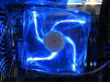
Here is the fan in action on top of the heat
sink.
 |
 |
The temperatures were measured with the
SpeedFan utility and noted after
the system reached steady state.
|
State |
CPU Temperature [°C] |
CPU Fan Speed [rpm] |
|
Idle (room 26.4°C) |
49 |
890 |
|
Prime95 (room 26.1°C) |
64.5 |
1200 |
|
3DMark2001SE (room 25.8°C, GPU 53.4°C) |
61.5 |
1200 |
Compare
these temperatures to the ones with a faster spinning 92 mm fan.
(6/5/2005) The IXtrema 120 mm fan does not run fast enough
to cool the CPU heat sink sufficiently. Instead it was put in place of the two
80 mm Papst fans at the rear of the case. A 3-pin male to 4-pin male
adapter cable was needed to connect the fan to the Y-adapter cable for the
CHA_FAN header of the main board. The 120 mm fan looks nice, runs very
quiet, and provides a speed signal to the BIOS. A spare Delta Electronics
92 mm fan with speed sensor (Model ASB0912H, 12V, 0.3A) was used as CPU
fan. It runs over twice as fast, somewhat noisy at full speed, but cools the CPU
nicely.
|
The 120 mm fan fits perfectly into the case at
the rear. Only one cable tie at the top right corner is needed to secure
the fan.
The remaining openings at the rear of the case were
covered with pieces of clear plastic. This forces outside air through the
air filter at the front. |
 |
The temperatures were measured with the
SpeedFan utility and noted after
the system reached steady state.
|
State |
CPU Temperature [°C] |
CPU Fan Speed [rpm] |
|
Idle (room 25.8°C) |
41 |
1875 |
|
Prime95 (51% CPU
utilization, room 26.6°C) |
54 |
2700 |
|
3DMark2001SE (room 26.3°C, GPU 54 °C) |
51 |
2700 |
|
Prime95 and 3DMark2001SE (100% CPU utilization, room
26.4°C, GPU 54°C) |
54 |
2700 |
Thermaltake Silent Cat 9CM CPU Fan
|
(6/19/2005) The Delta fan was replaced by a
Thermaltake
Silent Cat 9CM. This white 90 mm fan has multidirectional air intakes
for improved air flow while keeping the noise level low. It has a 3-pin
connector with speed signal.
The picture shows this fan mounted on the CPU heat
sink using the fan mounting wires. |
 |
Specifications:
|
P/N |
A2013 |
Fan
Speed |
2500±10%
RPM |
|
Fan
Color |
White |
Max. Air
Flow |
52.24CFM |
|
Fan
Dimension |
90x90x25mm |
Max. Air
Pressure |
2.84mmH2O |
|
Rated
Voltage |
12V |
Noise |
21 dB(A) |
|
Started
Voltage |
7V |
Bearing
Type |
1 Ball 1
Sleeve |
|
Rated
Current |
0.18A |
Life
Expectation |
60,000
hrs |
|
Power
Input |
2.16W |
Connector |
3
Pin |
|
Weight |
103
g(0.23lb) |
The resulting
power
consumption of the fans connected to the main board fan headers is still
safely below the maximum value.
The temperatures were measured with the
SpeedFan utility and noted after
the system reached steady state. This fan is very quiet even when running at
full speed.
|
State |
CPU Temperature [°C] |
CPU Fan Speed [rpm] |
|
Idle (room 26.3°C) |
45.5 |
1650 |
|
Prime95 (51% CPU
utilization, room 26.3°C) |
55.5 |
2300 |
Connections between PSU and Main Board
|
Connected the 20-pin power plug and the 4-pin ATX 12V
power plug from the power supply to the main board. |

 |
|
Initially, connected the rear and top case fans to
the power supply fan-only plugs. Connected a device power plug to the
front case fans.
Later, once the DigitalDoc5 device was installed, used
adapter cables to connect the front
case fans to the main board “CHA_FAN” header and the rear and top fans to
the DigitalDoc5.
 Connected the
power supply fan speed monitoring lead to the main board header. Connected the
power supply fan speed monitoring lead to the main board header. |
|
|
|
|
Front Panel Connections
|
Front panel connectors (labels on connectors face
away from case bottom unless otherwise noted):
- System power LED lead (label on connector faces bottom of case)
- Power switch lead
- Reset switch lead
|

|
- Speaker lead
- IDE LED lead (label on connector faces front of case)
|
 |
|
Connected the two black leads for the left USB ports
in the front of the case to the blue USB header on the main board with the
labels on the connectors facing away from the case bottom. |
 |
The vocal messages are not played through the internal PC
speaker. In order to hear POST Reporter vocal messages, connected rear line-out
to line-in of another computer/speaker amplifier.
POST stops with a “no system memory installed” message.
Notes
[1] Torture Test –
In-place large FFTs
[3] DigitalDoc5 sensor
glued to GPU heat sink
[4] Torture Test –
In-place large FFTs
[6] DigitalDoc5 sensor
glued to GPU heat sink
[7] Torture Test –
In-place large FFTs
|


